Hidden
Hidden
Hidden
Hidden
Hidden
Hidden
Hidden
|
RTD TEMPERATURE MEASUREMENT (°C)
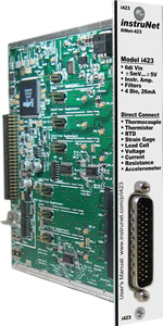
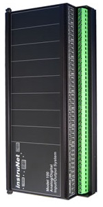
The following instruNet hardware supports RTD temperature measurements with the help of one user-supplied external shunt resistor:
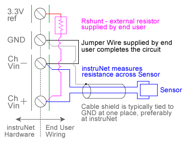
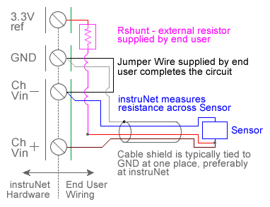
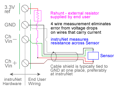
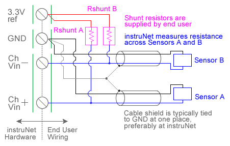
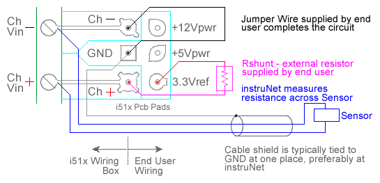
For quick setup instructions, click here. instruNet performs RTD temperature measurement using a voltage divider circuit; which involves connecting an RTD in series with a shunt resistor of known value, applying a voltage across the pair and measuring the voltage across the RTD, as illustrated above. The voltage across the RTD is measured between a pair of instruNet Vin+ and Vin- input terminals while the excitation voltage for the divider is supplied by the instruNet. instruNet calculates the temperature of the RTD device using the equations shown below, and returns "degrees C" engineering units. Alpha is the temperature coefficient of the RTD at 0°C and delta is the Callendar-Van Dusen delta constant. These constants are supplied by the manufacturer of the RTD, and are described in more detail below. Temperatures below 0°C are supported by instruNet software version ≥ 3.0; yet not in early versions. To do temperature measurement using an RTD in a voltage divider circuit you must wire your sensor per the above diagram and then set up your software via the Interview process (started after selecting sensor type in Channel Setup dialog) or by manually running through the below steps: 1. Set the Sensor field in the Hardware settings area to RTD. 2. Set the Wiring field in the Hardware settings area to Voltage Divider. 3. Set the Measurement Range in the Hardware settings area 4. For details, click here. 4. Set the Rshunt field in the Constants settings area to the ohms value of your Rshunt resistor. 1, 3, 6 5. Set the Ro field in the Constants settings area to the resistance of the RTD at 0°C, in ohms units (e.g. "100"). 6. If working with hardware that has variable internal excitation (e.g. i100 ± 5V), then set the Vout field in the Constants settings area to the desired excitation voltage 2, 11. Alternatively, if applying an external excitation voltage, enter -Ro value in the Ro edit field (e.g. -100 instead of 100 ohms) to tell the software that the excitation is external, and then enter the external excitation voltage in the Vout field. 7. Set the alpha field in the Constants settings area to the alpha value of your RTD. 8. Set the delta, Rlead field in the Constants settings area to the delta value of your RTD. 9. If working with temperatures below 0°C, set the the v_Poisson field in the Constants settings area to the beta value of your RTD. 10. Wire your RTD per one of the above wiring diagrams. Figures a, b, and c differ by the number of wires in the instrunet-to-RTD-device cable. Figure c (4-wire cable) is the most accurate and is therefore recommended. Note that the number of wires in the cable is different from the number of wires that eminate from the RTD device itself. For example, one can use Figure c (4-wire cable) with a 2-wire, 3-wire or 4-wire RTD device. Or use Figure a (2-wire cable) with a 2-wire, 3-wire or 4-wire RTD device. For details on the differences between wiring diagrams a, b, and c; and the temperature offset errors that one can expect from each, click here. 11. Click here if you need more guidance setting up the software, and click here if the measured value is not correct 5, 10. To reduce noise, 0.001 seconds of integration is often helpful (i.e. set the Integrate field in the Hardware setting area to 0.001). If you want a detailed report on your setup, press the Sensor Report button in the Channel Setup dialog. RTD Self Heating Vs. Excitation Voltage Many RTD manufacturers recommend that RTD resistance be measured with a 1mA current source since this often dissipates several milliwatts, and therefore does not cause noticeable "self" heating of the RTD device itself. An example would be a 100 ohm RTD (which will vary from 100 to 214 ohms as the temperature varies from 0°C to 300°C), a 3.3V excitation voltage and a 10K ohm shunt resistor. The average current and power dissipation of the RTD at 0°C would be:
Current (Amps) = Volts / Resistance = Volts / Ω The voltage across the RTD would vary from 32mV to 69mV as the resistance across the RTD changed from 100 to 214 ohms (corresponding to a temperature change of 0 to +300 Celsius); therefore, an input Voltage Range of ±80mV would be ideal with a 100 ohm RTD, 3.3V excitation voltage, and 10K ohm shunt resistor. The table below shows several standard RTD's. R_xxC refers to the resistance (Ω's) across the RTD device when it is at xx °C; whereas Ro refers to the resistance (Ω's) across the RTD when it is at 0°C. The A/B/C and the alpha/delta/beta coefficients describe the temperature vs. resistance curve as noted below.
A voltage drop occurs over each wire that carries current, as described below: Wire diameter is specified in units of "AWG" gauge, and there is a specific number of ohms-per-meter resistance for each AWG. For a list of gauges and their associated Ω/meter, click here (e.g. 0.133Ω/meter for 26 AWG). The 2-wire cable (e.g. Figure a) measures the voltage across the RTD with the same wires that carry current to the RTD, and therefore incurs a cable-induced temperature measurement error from two measurement wires. The 3-wire cable (e.g. Figure b) measures the voltage across the RTD with one voltage sense wire and one current carrying wire, and therefore incurs a cable-induced temperature measurement error from one wire. The 4-wire cable (e.g. Figure c) measures the voltage across the RTD with wires that are different from the current carrying wires, and therefore do not have any cable induced temperature measurement errors. To calculate the estimated temperature measurement error from a 2-wire or 3-wire cable:
For example: assume you have a 4 meters long 26AWG (0.133Ω/meter) 3-wire cable (Figure b) connected to a 100Ω RTD (~0.4Ω/°C). The expected error would be calculated as follows:
In summary: if you need high accuracy, or your cable wires are tiny, or your cable is long, then use 4-wire cable (Figure c). RTD Temperature Vs. Resistance Resistance is a function of Temperature
Temp ≥ 0°C: R (Ω) = R_0C * { 1 + A*t + B*(t^2) }
R (Ω) = resistance across the RTD in ohms units, when the RTD is at temperature t °C If one solves the above R = function(t) equation in the reverse direction, for temperatures above 0 °C, they get the following (temperatures < 0 °C are more complex)
R_RTD (Ω) = Rshunt * (Vin+ - Vin-) / (Vout - (Vin+ - Vin-))
R_RTD (Ω) = resistance across the RTD in ohms units, at temperature t RTD Coefficients
alpha = (R_100C - R_0C) / (100 * R_0C) Troubleshooting Your RTD Temperature Vs. Resistance Curve For details on temperature offset errors that one can expect from voltage drops on the instrunet-to-RTD-device cable, click here (e.g. ~2.6°C offset error with 4-meter 26-AWG 2-wire Figure a cable). To learn more about the t (°C) vs. R (Ω) curve being used by instruNet to calculate your RTD's temperature: Open the Network page, click on your RTD channel, press the Sensor Report button and then view your RTD's internal parameters in the "Your RTD" column of the RTD characterization table. Notice that this table compares your RTD with standard RTD's such as Iec751-1995. The Report button is supported in instruNet software version ≥ 3.0. Also note that temperatures below 0°C are supported by instruNet software version ≥ 3.0; yet not in early versions.
|