instruNet hardware is 100% plug and play for all computers. instruNet does not use dip switches,
DMA, low memory, interrupts, and I/O addresses. All you need to do is plug the Controller board into your
computer, connect your network devices, slap a terminator onto the end of your network and run the instruNet World
software. he instruNet driver automatically determines the physical locations of all installed Controllers and Network Devices.
Please keep in mind the following when designing and constructing your network:
1. Install up to eight i2x0/i60x controllers into each computer The number of available slots typically determines the number of controllers
(i.e. networks) that can be installed and simultaneously run on one computer;
up to eight i2x0/i60x controllers per computer. The software numbers each controller in the order
that they are found in the computer ("netNum" ranges from 1 to the number of Controllers). Each
controller manages its own network of devices. In most cases, only one controller is necessary. The
advantage of multiple controllers is that each is its own real-time machine,
and more controllers can do more things simultaneously. For details on working with multiple controllers, click
here.
2. Maximum number of high-speed digitize channels per i240/i60x Controller is between 100 and 256, depending on your specific setup
instruNet supports up to 256 channels per computer, as limited by the instruNet driver,
and this can be spread out among multiple i2x0/i60x controllers.
It can also support 256 channels on one i2x0 controller running in
scalar i/o mode (e.g. call subroutine to get one value); however,
there are some limitations with the maximum number of channels per i240 controller when running
high-speed digitize (i.e. instruNet driver does digitizing). Here,
instruNet supports a maximum of 100 channels per controller in the following two cases (otherwise, supports 256 per i240 controller):
digitize from i420/i430 (not i423) on the ≤ ±80mV voltage range
integrate each point (i.e. Integration field is set to > 0.0 seconds)
3. Install up to eight i100's or up to eight i4xx Card Cages on each i2x0 Network One can attach, in daisy-chain configuration, up to eight i100 Devices or up to eight i4xx Card Cages to each instruNet i2x0 Controller. For details on installing i4xx cards
into an i4xx Card Cage, click here. Each Network Device has two DB-25 connectors, one for network
input (male), and another for network output (female). To connect a chain of Network Devices, one must connect each input
connector to each output connector via a DB-25 Male/Female cable. The Controller is attached to the first device in the
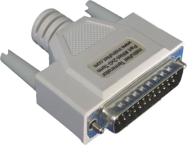
chain, and an instruNet Terminator is attached to the far end of the chain. Due to the male/female polarization, the network
cannot be installed incorrectly with instruNet Male-Female cables.
4. i200 Controller includes Timer I/O Channels The i200 Controller (not the iNet-230 PC-Card) provides 10 Timer I/O channels. Each channel can be programmed as a digital input, digital output (0V/4V TTL compatible), clock output, or period measurement input.
5. Each i2x0 Controller includes one Terminator One instruNet Terminator must be installed at the end of each network chain. This terminator mates with the output connector of the last device. instruNet Controllers include an instruNet Terminator, therefore they do not need to be purchased separately. Caution: Do not use a SCSI Terminator in place of an instruNet Terminator -- they are different.
6. Each Network Device includes one cable Each instruNet Network Device (i100 or i4xx Card Cage) is shipped with one 10 foot (3.3 meter) DB-25 Cable Male/Female cable for purposes of configuring your network.
7. You can purchase your own cables If you want a specific cable length, you can purchase your own DB-25 male to DB-25 female, shielded, wired point-to-point (i.e. pin X to pin X) cables. We recommend 24 gage wire for > 4 meters; however 28 gage is fine with ≤4m. Twisted pairs are recommend for >4 meters with the following wires twisted: 1 & 14, 2 & 15, 3 & 16, 4 & 17, 5 & 18, 6 & 19, 7 & 20, 8 & 21, 9 & 22, 10 & 23, 11 & 24, 12 & 25 (these are physically next to each other in the connector). Also, it is recommended that the drain wire (which is attached to the shield) be connected to the housing and pin #1 (GND) on both connectors. For more information on cables, please see
Db25f to Db25m Cables and
Low Capacitance Cables.
8. Minimum Base System One Controller and one Network Device is all you need to purchase to digitize waveforms, save them to disk, and view them. The i60x combine both Controller and Device into one tiny package.
9. Maximum Sample Rate As the physical length of the network increases, the maximum aggregate data acquisition sample rate decreases from 166Ks/sec maximum with a short network (e.g. 5 meters) to 4.15Ks/second aggregate with a long network (e.g. 300 meters).
This maximum aggregate rate applies to a batch of input channels from one i2x0/i60x controller. For example one instruNet network can support 4 voltage input channels at a maximum rate of 41.5Ksamples/sec for each channel (i.e. 166Ks/sec total aggregate throughput). The same network would allow 8 channels of voltage input to be acquired at 20.075Ks/sec per channel. The maximum aggregate rate can be increased by installing additional instruNet networks and controllers. For example, two controllers could support 332Ks/sec aggregate throughput if run simultaneously.
When the instruNet powers up, it empirically tests (i.e. it test the cable impedance) of the Db25 network to determine its maximum throughput rate (i.e. 4.15K/sec to 166Ks/sec). The maximum rate is decreased by: additional network devices, longer aggregate network cable length, non-twisted pair cables, and thinner cable wire (e.g. 28 gage instead of 24 gage).
10. Turn power OFF when cabling Always turn the computer and powered Network Devices Off before adjusting network cables.
11. Large Db25 networks require external power supplies The instruNet network Db25 cable provides power from the computer to the
external Network Devices (i100's or i4xx Card Cage's). As the number of
devices increases (more current drawn), and the cable lengths increases
(more voltage drops), it becomes increasingly necessary to add an external power supply for the Network Devices.
We recommend adding an external power supply if your cable is > 50 meters, or for every 4 Network Devices after your 3rd Device.
In other words, only add an external power supply if you have more than 3 network devices,
or if your network is longer than 50 meters.
12. Inject power close to i4xx Card Cage
Make sure the i300 power adaptor cable is connected directly
to the i410without a Db25 cable between the i300 and the i410, as noted
here. This is because a typical Db25
cable has small wires that do not transfer much power without excessive voltage drops.
 Hidden
Hidden
Hidden
Hidden
Hidden
Hidden
Hidden