There are two kinds of calibration: Factory Calibration and Software Calibration.
Factory calibration is done at the factory when the product is manufactured; and software calibration
is done in the field to remove further errors due to time ("stability") and temperature ("drift") change.
Software calibration is divided into several components:
Internal measurement circuitry software calibration -
Measure internal errors that are automatically subtracted when later voltage measurements are performed.
i4xx 3.3Vref readback with A/D - Read the i4xx 3.3V reference voltage with the A/D. This reference is used with several sensors such as RTDs, Thermistors and strain gages.
Thermocouple cjc screw terminal calibration - Measure i100 or i51x screw terminal temperature, which is needed when doing thermocouple measurements.
Check for i4xx power cycle - Looks for i4xx Card loosing power and shows an alert accordingly. If hardware looses power, then it will need to be reconfigured by the software.
i100 offset temperature drift calibration - Calibrate out a small errors (e.g. 10μV) that occurs when the i100 box changes temperature.
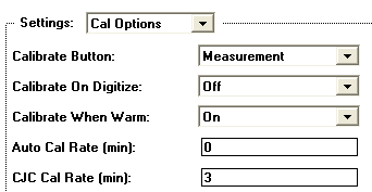
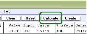
The Full software calibration, which includes all of the above components, occurs when the system is reset (i.e. press RESET button,
load .prf configuration file, or start instruNet software), and when the system is Software
Calibrated (i.e. press CALIBRATE button, issue software calibrate command, or set up software
to auto-calibrate every X minutes). The rate of software auto-calibration is set in the
Calibration Options dialog, as described below. Full calibration does not run if digitizing at any sample rate.
Calibration While Digitizing
If digitizing at a fast rate (e.g. > 1Ks/s/sec/ch), then no calibration of any kind occurs. However,
if digitizing slowly (e.g. ≤ 1Ks/sec/ch), then the 4 lower items in the above list (e.g. 3.3Vref, Cjc,
i4xx power, i100 temp drift) continue to operate.
Calibration Options Dialog
instruNet software Version ≥1.40.1.1 contains a Calibration Options dialog that provides several calibration
options, as described below. Calibration is helpful at reducing errors that occur when the measurement circuitry
internal temperature changes. This dialog, shown below, is accessed by pressing the Setup
button in the Record page and then pressing the Calibration button.
Programmatically, one accesses these fields via {netNum=0, devNum =0, modNum=1, chanNum=3, settingGroup = -21 =
sgt_CalOptions, fieldNum = 1 to 8 (e.g. 5 = fldNum_CalOptions_CjcCalRate)}. For information on setting these fields
programmatically, please see Calibration Routines.
For information on setting these with Visual Basic, please click here.
CAL BUTTON
There is a button in the Network page called "Calibrate", as illustrated to the right. And there is a popup menu in the Calibrate dialog box called "Calibrate Button", shown above, that controls the function of this Calibration button at the top of the Network page. The popup menu is set to one of:
Measurement - instruNet hardware is fully software calibrated when the Network Calibrate button is pressed.
Bal Gages - instruNet hardware is calibrated and all strain gages and load cells are balanced when the Network Calibrate button is
pressed.
Bal Bridges - instruNet hardware is calibrated and all bridges (i.e. strain gages, load cells, and pots) are balanced when the
Network Calibrate
Bal VDividers - instruNet hardware is calibrated and all voltage dividers are balanced when the Network Calibrate button is
pressed.
"Balancing" involves reading the voltage across a sensor and placing it into the "Vinit" field within the Constants settings area. This
is done to establish a zero point from the sensor, and should be done when the sensor is not receiving a stimulus (e.g. Load Cell with 0 Kg applied).
CAL ON DIGI If this popup menu is set to On, the instruNet hardware is automatically calibrated when one begins to
digitize (e.g. user presses Start button in Record page).
CAL ON WARM If this popup menu is set to On, the instruNet hardware is automatically calibrated 10 minutes and 25 minutes after the instruNet
software is first run.
AUTO CAL RATE This field, which is accessed by clicking {Record tab, Setup button, Calibrate button}, sets the rate that instruNet measurement
electronics is automatically calibrated, in units of minutes. For example, if this field is set to 5, then instruNet hardware is automatically
calibrated every 5 minutes. If set to 0, the Auto-Calibrate feature is disabled. The minimum rate is .016 minutes. During calibration, as much as possible is calibrated (e.g. full calibration if not digitizing, no calibration if digitizing at fast rate (>1Ks/s/ch) and several items are calibrated if digitizing at a slow rate.
For details on i100 auto-calibration while digitizing, click here.
Working With Thermocouple Sensors
In order to calculate the temperature of a thermocouple tip, one must know the temperature of
the screw terminals that attach the thermocouple wire to the measurement system (e.g. i51x or i100 screw terminals). This is sometimes referred to as "Cold Junction
Compenstation", "Cjc Calibration", or "Cjc". If at least 1 thermocouple is connected
to the system, this Cjc Calibration (i.e. measuring the temperature of the screw terminals) occurs when a Full
Calibration occurs (e.g. at the Auto Cal Rate), or when a Cjc Only Calibration occurs (e.g. at the Cjc Cal Rate).
CJC CAL RATE
This field, which is accessed by clicking {Record tab, Setup button, Calibrate button}, sets the rate that instruNet hardware
automatically performs Cjc Calibration, in units of minutes. CJC, as noted above, is used only with thermocouple sensors. If the CJC CAL RATE is set to 0, this feature is disabled. The minimum rate is 0.016 minutes. Reading the cjc sensor can occur while
digitizing at slow <1KHs/sec speeds and when the sum of the integration time is less than 40% of the sample period. If the iNet
hardware reads the screw temperature, and the screw then drifts by X degrees before the next CJC cal,
one will incur a thermcouple measurement error by that amount (since the software subtracts the screw terminal temperature when
calculating the thermocouple temperature).
THERMOCOUPLE DRIFT ERRORS
When working with thermocouples, it is recommended that AUTO CAL RATE be set to 5 minutes (i.e. to do a full calibration every 5 minutes) and CJC CAL RATE also be set to 3 minutes (i.e. to calibrate errors from temperature drift of the iNet screw terminals). If reading temperatures via the single value read/write GetChannelValue() routines, both AUTO CAL and CJC CAL will function at their perscribed rates. For details on AUTO CAL and CJC CAL, please see the above discussions. For differences between single value read/write and high speed digitize, please click here.
See Troubleshooting Thermocouples, for more information.
Advanced Techniques
AUTO-CALIBRATE UPON COMMAND
For information on forcing the calibration with DasyLab, please see SET PARAMETER ICON. If programming, see Calibration Routines. One
line of program code can tell the instruNet hardware to auto-calibrate.
ENABLING A BEEP WHEN CALIBRATION OCCURS
With instruNet ≥ v1.31.6, if you have a text file named "iNetLoad.ibs" in directory
"..program files\instrunet\end user\" and the file contains "Calibrate CjcBeepOn" text, a beep will sound when the cjc calibation is done; and if it contains "Calibrate BeepOn" on a separate line, a beep occurs when regular instruNet device calibration is performed.
GETTING ERRADIC READINGS INDEPENDENT OF CALIBRATION SETTINGS?
Attaching a little wire between instruNet GND and the Vin- screw terminal often fixes thermocouple problems. If that does not fix it, please see Noise Reduction Techniques.