Hidden Hidden Hidden Hidden


THERMISTOR TEMPERATURE MEASUREMENT (°C)
APPLICATIONS > TEMPERATURE MEASUREMENT >


Measurement Hardware

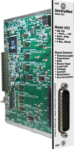
The following instruNet hardware supports Thermistor temperature measurements with the help of one user-supplied external shunt resistor:

i420 / i423 / i430 i60x i100


Wiring Diagrams

a) Thermistor Measurement with i4xx/i60x Hardware, Differential Wiring
b) Thermistor Measurement with i4xx/i60x Hardware, Single-Ended Wiring
c) Thermistor Measurement with i51x Wiring Box Pads, Differential Wiring
d) Thermistor Measurement with i100 Box, Differential Wiring

Quick Setup Instructions

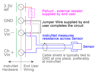
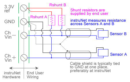
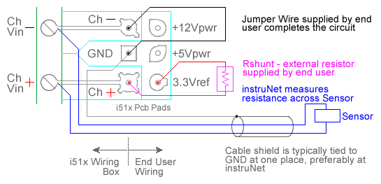
For quick setup instructions, click here.

Detailed Setup Instructions

Thermistors are two wire devices who's resistance varies with temperature in a known fashion, often accurate to ± 0.2°C.  The instruNet thermistor measurement feature supports ysi-Omega 100Ω to 1MΩ 4xxxx or 4xx series thermistors (not to be confused with instruNet i4xx cards) between the temperatures of -80°C to 250°C. Also, instruNet can measure temperatures from other types of positive and negative thermistors, provided that the end user specifies their Steinhart & Hart Coefficients (click here for details). When Thermistor is selected in the Sensor popup menu, instruNet assumes a thermistor is connected as shown in the above illustrations, and subsequently returns the thermistor temperature in degrees C units after applying a Steinhart & Hart resistance-to-temperature conversion.

To do temperature measurement using an thermistor, you must wire your sensor per the above diagram and then set up your software via the Interview process (started after selecting sensor type in Channel Setup dialog) or by manually running through the below steps:

1.   Set the Sensor field in the Hardware settings area to Thermistor. This will cause a series of dialog boxes to appear, asking the user several questions about the thermistor type (i.e. resistance at 25°C), shunt resistor value, and excitation voltage. It recommends a shunt resistor based on the thermistor in use and the temperature range of interest 1, 3, 6. In many cases, the recommended values work the best. Based on the responses to these questions, instruNet loads the following fields in the Constants setting group:

  • Ro - thermistor resistance at 25°C, in units of ohms
  • Rshunt - actual shunt resistance, in units of ohms
  • Vout - excitation voltage
  • alpha- the 'a' Steinhart & Hart coefficient
  • delta,Rlead - the 'b' Steinhart & Hart coefficient
  • GF - the 'c' Steinhart & Hart coefficient
  • V_poisson -  In version 2 software, this was the maximum expected temperature, in degrees C units. In version ≥ 3 software, maximum temperature is specified in the Hardware Measurement Max field.
  • Vinit - In version 2 software, this was the minimum expected temperature, in degrees C units. In version ≥ 3 software, minimum temperature is specified in the Hardware Measurement Min field.

instruNet also sets the Measurement Min/Max fields in the Hardware settings area.  The smaller the temperature range, the better the accuracy; therefore one should not make the specified range unnecessarily large.

If one sets the three Steinhart & Hart coefficients (i.e. a, b, c) to "0" or "auto"; then the software automatically calculates these given the measurement min/max and the thermistor resistance at 25°C.

If you want to run through the dialog box interview again, press the Interview button.

If you want to manually set any of the fields in the Constants settings group, do the interview, and then set them to your liking, after selecting Constants in the Settings popup.

2.  Wire your thermistor per the above figure. Click here if you need more guidance setting up the software, and click here if the measured value is not correct. 5, 10. To reduce noise, 0.001 seconds of integration is often helpful (i.e. set the Integrate field in the Hardware setting area to 0.001). If you want a detailed report on your setup, press the Sensor Report button in the Channel Setup dialog.

Theory of Operation

Measuring a thermistor temperature from an electrical point of view involves a voltage divider circuit. This uses a shunt resistor of known value and a reference voltage across the shunt resistor and thermistor, as illustrated above. The voltage across the thermistor is measured between the instruNet Vin+ and Vin- input terminals while the excitation voltage for the divider is supplied by the instruNet.  instruNet calculates the thermistor resistance using the following equation:

R_therm (ohms) = resistance across thermistor
    = Rshunt * (Vin+ - Vin-) /  (Vout - (Vin+ - Vin-))
 
Temperature_therm (°C)
    = -273.15 + 1.0 / [a + b {Ln( R_therm ) + c (Ln( R_therm )}3]

The a, b, and c constants in the above equation are a function of 3 points in the resistance-to-temperature table, and are calculated by instruNet software after the user completes a short dialog box interview. These parameters are sometimes referred to as "Steinhart & Hart Coefficients" or "Steinhart & Hart Parameters". Also, these a/b/c parameters are sometimes referred to as A/B/C (capital letters) in thermistor literature.

Setting Up A Non Ysi/Omega 4xxxx or 4xx Series Thermistor

If you want to set up a positive or negative thermistor that is not a Ysi/Omega 4xxxx or 4xx Series Thermistors then one must:

  • Decide on the temperature range of interest (e.g. 0 to 100°C).
  • Obtain the temperature vs resistance table from your thermistor supplier. This shows for many temperatures the corresponding resistance that would occur across the thermistor device.
  • Given the minimum temperature and maximum temperature of the range of interest, calculate the middle temperature (e.g. on 0 to 100°C range, the middle would be 50°C).
  • Given your 3 points (minimum/maximum/middle), identify their corresponding resistances in the temperature vs. resistance table. If your table does not specify the exact temperatures, then use the closest.
  • Enter these 3 points (3 temperatures and 3 resistances) into a steinhart & hart coefficient calculator. This returns the a/b/c steinhart & hart coefficients given 3 temperature points. For an example of such a calculator, click here or here.
  • Run through the instruNet thermistor interview assuming you have a standard ysi/omega thermistor. Accurately specify the thermistor resistance at 25°C.
  • When the interview is finished, enter your a/b/c coefficients in the Constants area (i.e. select Constants in the Settings popup menu):
    • alpha- the 'a' Steinhart & Hart coefficient
    • delta,Rlead - the 'b' Steinhart & Hart coefficient
    • GF - the 'c' Steinhart & Hart coefficient
  • Check your work by pressing the Sensor Report button in the Channel Setup dialog. It will display a temperature vs resistance table for your setup. Check this against the temperature vs. resistance data that you received from your thermistor supplier.
  • For more information, see Theory of Operation, Thermistor or Steinhart/Hart.

Example:
Assume we have a 10K thermistor and its datasheet says its resistance is 44308Ω at -10C, 4100Ω at 50C, and 949.73Ω at 100C. We plug these numbers into this calculator and determine: a (alpha) = 0.8486419218e-3, b (delta,Rlead) = 2.609816635e-4, and c (GF) = 1.300347927e-7. The calculator output is shown below.


Thermistor Self Heating

To minimize "self heating", it is recommended that thermistors operate at less than 100 μWatt. In other words, the energy that is pumped into the thermistor device itself to do the device resistance measurement, which causes the device to heat up a little, should be ≤ 0.0001 Watts. For example, a 2252 ohm thermistor that measures temperatures in the 0 to 70°C range with a 3.3V excitation voltage (thermistor varies between 394.5 and 7355 Ω) and 10KΩ ohm shunt resistor would see 37μW at 70°C; as noted below:

Current (Amps) = Volts / Resistance = 3.3V / [10000 + 394.5] = 0.31mA
Power (watts) = Current^2 * Resistance  = .00031^2 * 394 = 37μW

In this case, the voltage across the thermistor varies from 122mV to 1.45V as the resistance across the device varied from 394 to 7355 ohms; therefore, an input Voltage measure range of 0 to 2.5V would suffice. For recommended shunt resistors, click here.

Thermistor Measurement Errors

The maximum thermistor measurement error is the sum of the following component errors:

  1. Errors within the thermistor itself (typically ± 0.1C to ± 0.2C). For more details, please consult your thermistor supplier.
  2. Thermistor linearization error: ± 0.05C.
  3. Shunt Resistor Accuracy Error

    This is dependent on the type of shunt resistor in use, the specific thermistor in use, and the temperature one operates at. For example, if you use a 0.025% initial accuracy with 20ppm/°C shunt resistor, then its initial accuracy can be off by as much as 0.025%, which causes a 0.025% error in the thermistor resistance measured by instruNet. For example, a 2252 ohm thermistor at 0C has a resistance of 7355 Ω, and this value multiply by 1.00025 is 7356.8, which corresponds to a 0.005C error. Please consult your thermistor resistance-to-temperature tables when making these calculations. In most cases, a 0.025% shunt resistor with a 20ppm/°C temperature coefficient provides less than a 0.01°C error. For a list of recommended resistors, click here.
  4. Thermistor voltage measurement errors

    These are due to the voltage measurement accuracy of the instruNet hardware. Typical measurement accuracies are ±500uV, ±75uV, ±15uV, ±10uV in the ±5V, ±.6V, ±80mV, ±10mV ranges, respectively. instruNet measures two voltages, the voltage divider excitiation voltage, and the voltage across the thermistor itself (both introduce a small error). The thermistor resistance is calculated with the following equation:

    R_thermistor
        = R_shunt * Volts_thermistor / (Volts_excitation - Volts_thermistor)

    Where:

    R_thermistor = calculated thermistor resistance in ohms
    R_shunt = shunt resistor resistance in ohms
    Volts_thermistor = voltage measured across the thermistor
    Volts_excitation = excitation voltage across the voltage divider

  5. Shunt resistor self-heating

    The power dissipated by a resistor (shunt resistor or thermistor) is:

      Power_Dissipated (Watts) = (Volts_Across_Thermistor * Volts_Across_Thermistor / Resistance).

    This power causes the resistor to heat up:

      Temp_Change (C) = Thermal_Resistance (C/Watt) * Power_Dissipated (Watts)

    And this causes a change in resistance. For a Resistor:

      Change_In_Res (ohms) = Temp_Change (C) * Temp_Coeff (ppm/C) * Res_Value (ohms)

  6. Thermistor thermal self-heating

    This is calculated in the same manner as the Shunt resistor self-heating above; however, it is not necessary to calculate the Change_In_Resistance in the end, since the 2nd equation already provides the change in temperature, which is the error of the thermistor heating up on its own due to current passing through it. In most cases, one should put ≤ 100uW through a thermistor to keep its self heating < 0.07°C. For more details on thermistor self heating, click here.