THE i4xx CARD or i4xx CARD CAGE IS NOT SEEN BY
INSTRUNET SOFTWARE OR SHOWS ERROR ALERT TROUBLESHOOTING > i100 DEVICE >
Things to Try
CAUTION: If one physically attaches instruNet devices while power is applied, it is possible for the incorrect voltages
to be applied to the circuitry for very short periods of time, causing damage. Also, plugging non-instruNet
equipment into instruNet Db25 connectors can also cause damage.
To avoid permanent damaged to instruNet hardware:
i60x:
Unplug USB cable to i60x device while wiring
sensors and while plugging into i60x Hd44 Connector
i4xx/i555:
Remove 110/220 VAC power to i312.8 power supply while wiring sensors
and
while connecting i51x wiring box to Hd44 Connector
If an i2x0/i60x Controller is not seen by instruNet software, click here.
If an i100 box is not seen by instruNet software, click here.
The i4xx Card Cage requires 5V, +12V, and -12V power in order to operate. If these are present, the i410 front panel red power light illuminates.
If this light is off, then:
If the i4xx Card Cage is powered from an i312 desktop power supply:
Check the green power light on the i312 power supply. If this is off, then you need to attach 110/220 VAC power to the i312.
Make sure the i300 power adaptor cable is connected directly
to the i410without a Db25 cable between the i300 and the i410, as noted
here. This is because a typical Db25
cable has small wires that do not transfer much power without excessive voltage drops
If the i4xx Card Cage is connected to an i230 PCMCIA controller, then make sure you installed a i312 power supply before the i410, as illustrated
here.
If the i4xx Card Cage is connected to an i200 PCI controller and you have ≥ 4 cards in the i4xx Card Cage,
then it is recommended that you install an i312 power supply immediately before
the i410 interface card, as illustrated here.
This is because the amount of power transmitted out of the i200 is limited,
and the Db25 cable involves voltage drops when too much power is transmitted over its small wires.
At this point in the diagnostic proceedure, the following are all true:
The i2x0 Controller is seen by instruNet software.
The i41x red power light is on, indicating the i4xx Card Cage is receiving power.
Power the computer Off and then On, and note that only one instruNet program can run at a time.
Upgrade to the latest iNet32.dll, per the instructions here (this is free). To see the version of your currently installed iNet32.dll,
run instruNet World software and select About under the Help menu.
All i4xx Cards require version ≥ 3.0.
Make sure the cables attached to the i41x interface card and the i2x0 controller are secured properly to their mating connectors.
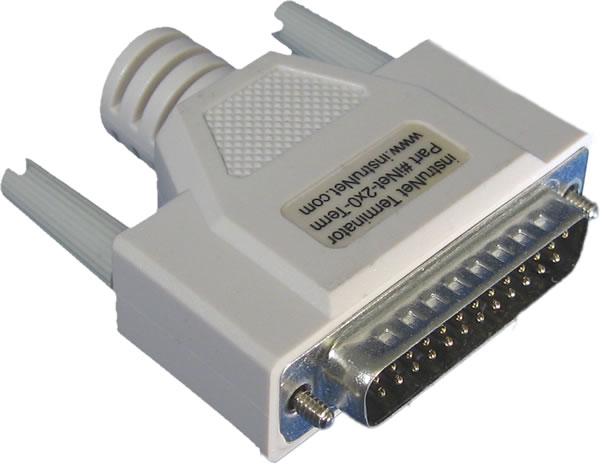
If the instruNet Db25 network is longer than 5 meters (15ft),
then one must place an instruNet Db25 Terminator at the end of the network,
as described here.
Start instruNet World software while physically viewing the green I/O light on the i41x Interface card.
This should blink for 0.5 seconds after each communication with the i2x0 controller.
During instruNet World startup, it should illuminate for several seconds.
If this does not occur, then at least one of the following is true:
i2x0 controller is not attached to i41x Interface Card -- check cables.
At least one faulty wire exists between i2x0 controller and i41x Interface Card
-- try another cable if possible, try wiggling cable and see if that has an effect (indicating intermittant connection), tighten thumbscrews at connectors.
There is an internal problem with i41x interface card -- try another i41x card, if possible.
There is an internal problem with a non-i41x card in card cage that is effecting i41x card -- with i4xx card cage power OFF remove non-i41x cards and see if that fixes it.
There is enough power to cause i41x red light to illuminate, yet not enough to fascillate communication with i2x0 controller (this is rare)
-- check power supply voltages with handheld volt meter, as described here.
At this point in the diagnostic proceedure, the following is true:
The i41x green I/O light illuminates when instruNet World software starts up, indicating
the i41x is internally working and the connection between the i2x0 controller and i41x is working.
If you have an i51x wiring box attached to one of your i4xx cards, then you can check the +5V/+12V/-12V power supply voltages at the i51x screw terminals
with a handheld volt meter. Place meter leads between
GND and 5/12/-12V screw terminals to measure each of these 3 voltages. You should see 5V ±0.4, 12V ±0.8, and -12V ±0.8.
If working with an i2x0 controller, try another DB25 male to DB25 female cable, if possible. These are 25 wire pin N to pin N cables (where N varies from 1 to 25), available from most computer stores.
Try the instruNet hardware with another computer, or another i2x0 controller, or try another i4xx Card Cage. This will help determine if the problem is the computer, i2x0 controller, or i4xx Card Cage.
To identify if this is related to a buggy mechanical connection within wiring/cables: Run instruNet World,
press the TEST tab at the bottom of the window, press the BIG TEST button to test continuously until you mouse
down or an error is seen (in which case, an alert appears), and then pull / wiggle wires and connectors while
looking for that alert. If poking at a specific place consistently produces an alert, you have a bad connection at that place.
To identify if this is related to temperature (heat expands materials causing buggy connections to be Intermittent),
blow heat or cold (e.g. hair dryer, heat gun, place in fridge for 20 minutes, cold spray), while running Big Test (described above) and looking for an alert.
The instruNet i2x0 Db25 chain involves 25 wires which travel from the controller card to the terminator at the end of the chain.
These are straight thru on all connector pins, except for pins 7 and 20. In other words, one can use an ohm
meter to see close to < 1 ohm between pin X at the male DB25 connector that attaches to the i2x0 controller card,
and pin X at the female DB25 outgoing connector at the last instruNet box (except for pins 7 and 20). Therefore,
one can check their cable with an ohm meter. If < 1 ohm is not seen on a pin (other than 7 and 20), there is a problem.
If one wiggles the wires/connectors and a resistance fluctates, there is a problem.
If your instruNet Db25 cable is long (e.g. > 50meters), try removing terminator (which might excessively load down data signals).
If you have many (e.g. > 4) instruNet devices (i.e. i100 boxes or i4xx Card Cages) attached to one i2x0 controller, and these devices are physically close to each other,
consider placing a 0.3meter DB25male-to-DB25female cable between each device, instead of the standard 3meter cable.
Press the SCRIPT tab at the bottom of window, enter debug cable
in the text window, press the EXECUTE button, press the SAVE AS button to save the resulting text to a file, and email this file to your instruNet Supplier.
 Hidden
Hidden
Hidden
Hidden
Hidden
Hidden
Hidden